| 123456789_123456789_1 | 123456789 | 
Figure: Elevation Front (4K)
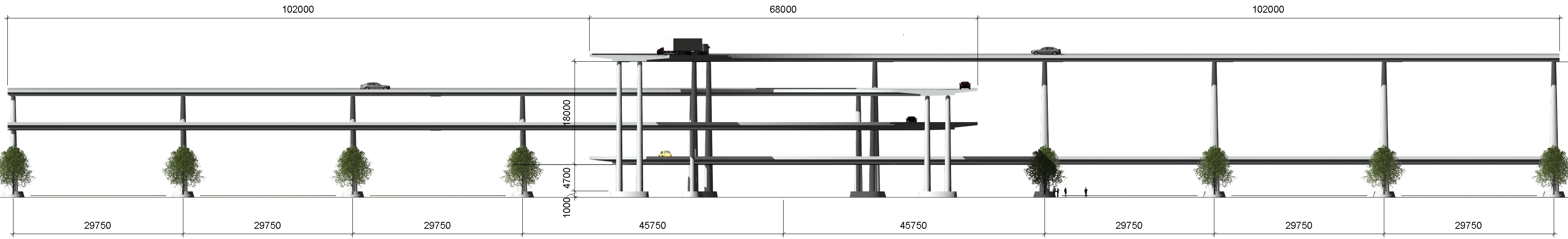
Figure: Elevation Back (4K)

Figure: Elevation Left (4K)
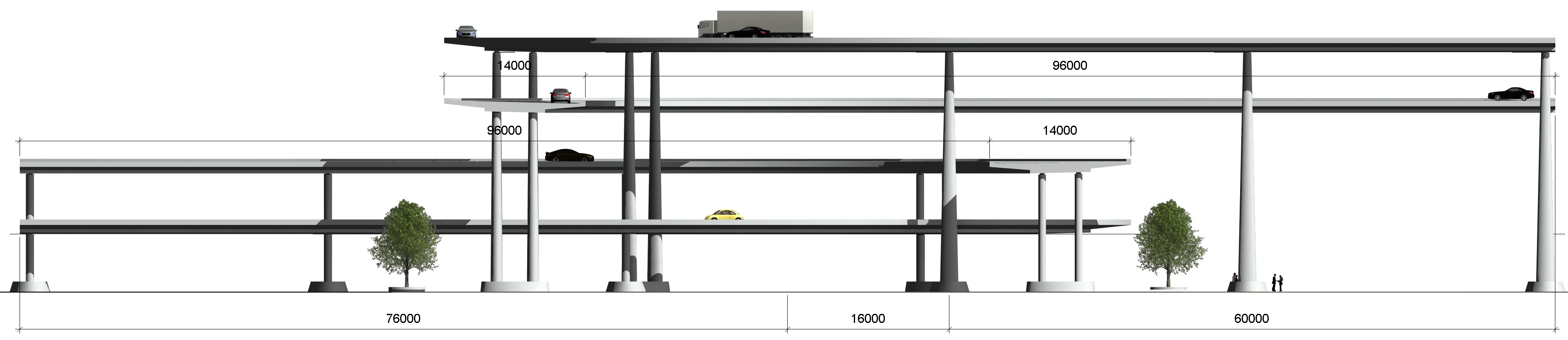
Figure: Elevation Right (4K)

Figure: Section 1 (4K)
Working in ICDAS it is not about what we model but how to model it. The 4-levels concrete bridges have been automated only for one bridge, then mirror-copied to the other three manually, if the four alignments are symmetrically in XY-Plan at the crossing. ICDAS COB 2018.02 automates bridge deck in Revit by reading XYZ coordinate of alignment, which can be a combination of rectilinear lines, circular arcs, clothoid or any curved lines needed for the road geometry. Alignment is designed in AutoCAD Civil3D (or Bentley Power Civil, InRoads, InRails) and export to points coordinate in *.html file. The users can open that html file directly from Excel, then copy and insert XY-coordinate to ICDAS Excel input to automate the deck. In this example a fictive alignment created in Excel composing of a circular arc and two rectilinear tangent lines at the ends. The circular arcs have radius 50m at the long edgebeam outer line and 50-14=36m at the short edge beam where 14m is width of the deck. In the Plan view a 12m long truck shown at the short radius where the vehicle speed is 30km/h for minimum radius 30m (36m in the example). The different height of decks, and thereby the piers, can be easily adjusted when loading the pier family into the decks (from ICDAS libraries of the piers). The highest pier 22663mm is designed with increasing bending stiffness towards the bottom. ICDAS designs the components of bridge in family files. Thus, the user is completely outside the complexity of the bridges crossing of heavy graphics. E.g. a single pier is designed, automated or modified from a simple family file of only 440KB, and be loaded into the bridges crossing immediately. The users can also change family files of the piers for meaning of using family files in Revit BIM. Refer an ICDAS subscription for libraries of bridge family and guider how to use smart parametric Revit family objects, and ICDAS COB to automate the bridges in Revit and Lusas. In the example the four decks have been created in one Revit file as the symmetric alignments assumed from the start. Otherwise, the users automate each bridge in a family file then load them in a project file for the entire crossing. Doing so, each bridge can be modified individually and concurrently, an opportunity to drive the project four times faster if four employees are available. Project file will also be updated four times faster when only one bridge modified, instead of four bridges from one family file must be updated in this case. Finally, note that most of works can be done in family files but you can Go Live only from project file for Revit LIVE & Virtual Reality.
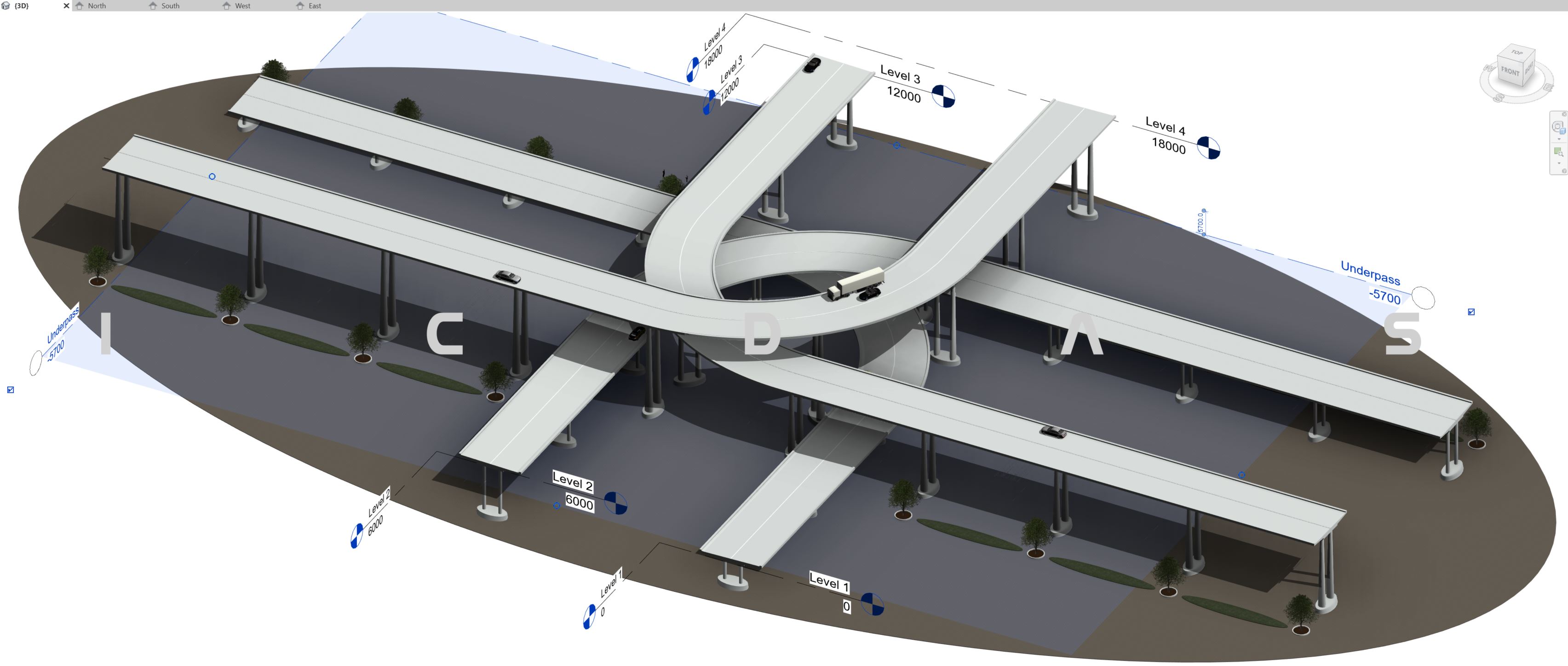
Figure: Revit 2019, Levels in 3D View (4K). Updated 20-06-2018
In Revit 2019 the user can drag the extents of the levels in 3D View. The above figure shows the level 1, 2, 3 4 drags to the Bridge 1, 2, 3 4. The elevations are relative, which will be automatically updated once a true point is entered at Project Base Point. Also, from Revit 2019 all opening views are shown on top of the drawing area.
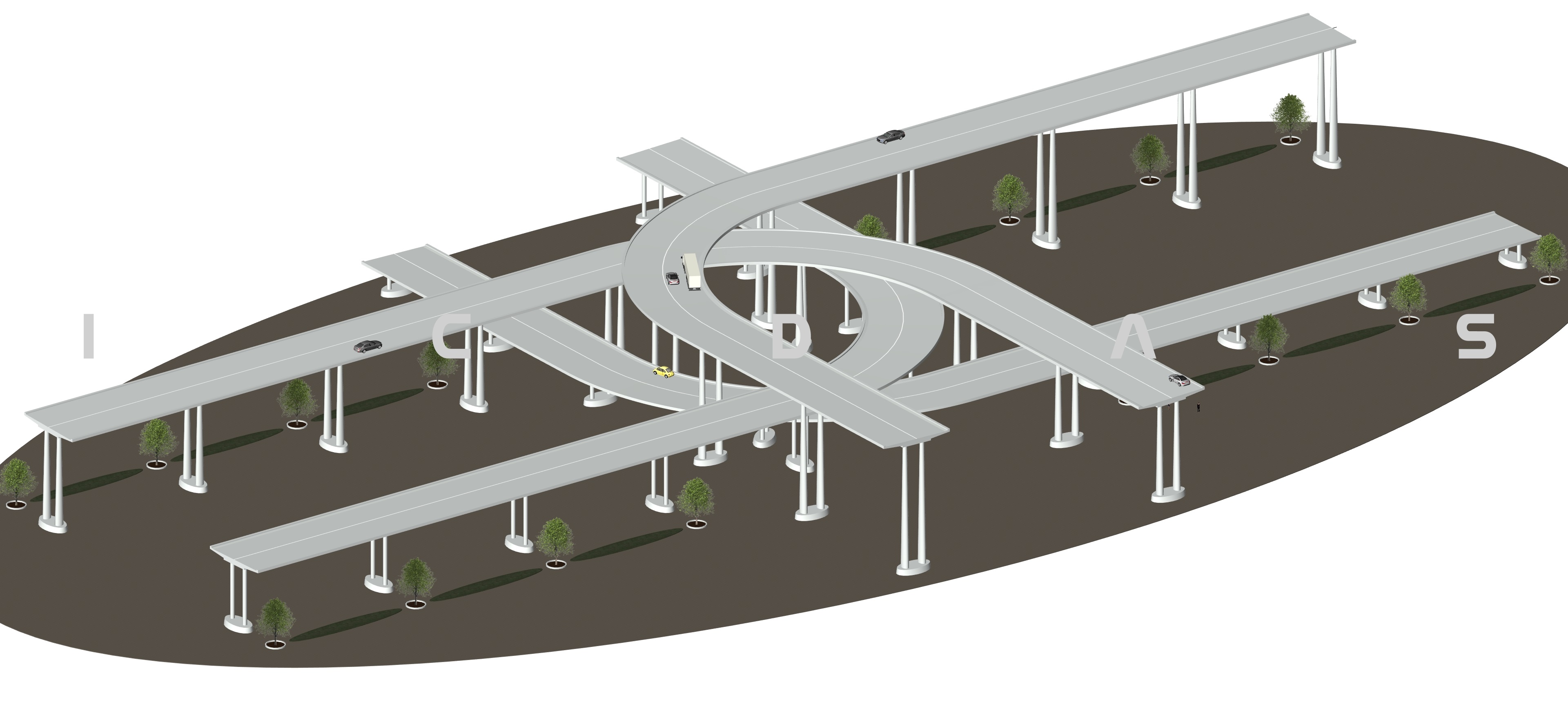
Figure: 3D View (4K)

Figure: 3D View (4K)
Back to Top Menu
|


