S o f t w a r e     f o r     a u t o m a t i c     c r e a t i o n     o f     m o d e l s     u s i n g     p a r a m e t r i c     d a t a

123456789_123456789_1123456789Concrete Bridge Software 

Model Examples
ICDAS YouTube Channel   ICDAS COB 2020.00R

Road Bridge Model Examples
  123456789_123456789_123456789_123456789_123456789_123123456789_123456789_123456789_123456789_123456789_123456789_123456

Concrete Bridge

Model Examples


Model description


Input


BIM model


Analysis model


Landscape model


ICDAS Basis of Design


Workflow of Software


Additional features


Rendering, Animation &
Vitural Reality  


Case study


Subscription 


123456789

08-01-2017


Double Curved Concrete Slab Deck & Reinforcement

ICDAS COB Option 3 (Dynamo)


(Concrete geometry of this bridge deck)


Key words


Base rebar, multi-rebar creation start, end and step. Save and manage selected rebar.


This section generates rebar in double curved concrete bridge deck outlined in previous page.

The employed Dynamo scripts are based on Dieter Vermeulen, Autodesk.


Geometry of the curved deck is resumed below:

Span length: 7380+29520+29520+7380mm (along center alignment)

Stations step: 2460mm (along center alignment)

Alignment radius: 100+7.460m (100m to the outer line of the right edge beam)

Slopes of cross section: 2.0, 1.6 and 11.1%

Slope of alignment vertical: 0.1%


Note that the slope of alignment vertical was 5% in the previous section which give vertical errors for the generated

rebar. This issue is in under investigation.


The shapes, diameter and spaces of rebar are not in focus of this example sin they are all parametric in Revit and

Dynamo. The standard diameter 12 (for stirrups) and 16mm for bending reinforcement in space 200m are used. The

focus of example is to control automation of distribution of rebar along a selected edge line in a double curved bridge

deck, both vertical and horizontal positions. It should be noted that once the 3D reinforcement created, one can create

any 2D sectional drawing report as needed with Revit. Also reinforcement schedules reported incl. quantities, types,

name of partitions of rebar and so on can be created in Revit. Once the 3D rebar redesign, all 2D drawings and schedules

are automatically updated. These features are not outlined here. 


Figure: 3D reinforcement in bridge deck (concrete deck not shown)

123456789_123456789_1


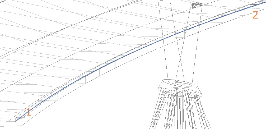
The needed base rebar


There are five single base rebar needed for creation of multi rebar along a selected edge line. These base rebar are

created over the center Pier2 as shown below


Figure: Base rebar


where


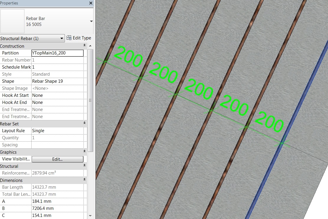
Base YTopMain16_200: Transverse (Y) Top Main reinforcement, diameter 16 space 200mm at center alignment


Base YTopMainSlop16_200: Transverse (Y) Top Main reinforcement at the right slope, diameter 16 space 186mm at

                                         the inner line right edge beam


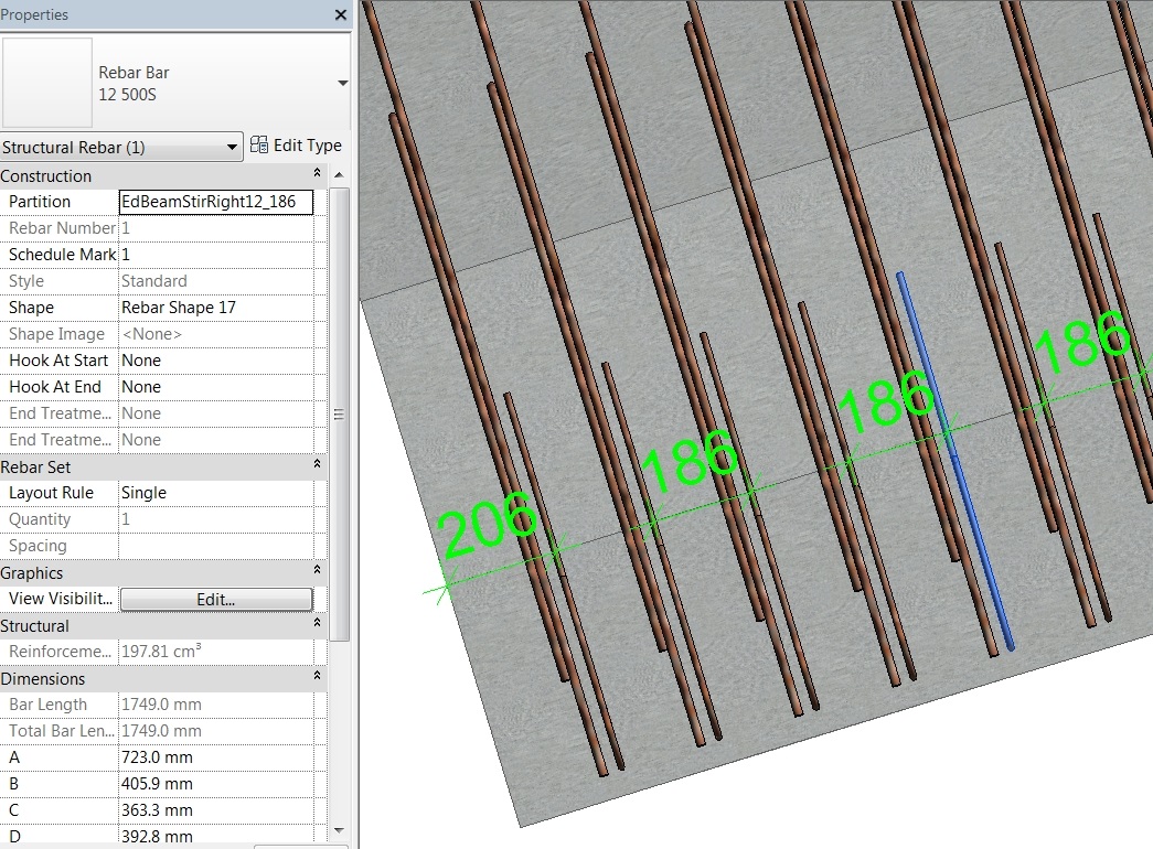
Base EdBeamStirRight12_186: Edge beam stirrups Right, diameter 12 space 186mm at the inner line right edge beam


Base EdBeamStirLeft12_214: Edge beam stirrups Right, diameter 12 space 186mm at the inner line left edge beam


Base YBotMain16_200: Transverse (Y) Bottom Main reinforcement, diameter 16 space 200mm at center alignment


Each single base rebar will be used to create mufti-rebar along a selected edge line. Once YTopMain16_200 created,

we measure the distance 186 and 214mm at a-two-rebar at the inner line of the right and left edge beam, respectively.

These rebar spaces are shorter and longer than 200mm at the center alignment because the curved lengths are shorter

and longer at the right and left edge beam, respectively. Note that the center alignment has a horizontal radius of only

100m. The smaller radius gives the bigger different of space of the transversal rebar at the right and the left edge beam.


In this example the deck cross section has slope 2% downward from left to center, 1.6% from center to 540mm

before the right edge beam inner, then slope up 11.1%.


Save the base rebar and multi-creation rebar


Once the first base rebar YTopMain16_200 created, save it as ‘Base YTopMain16_200’ (Revit > Manage tab > Selection

panel > Save). Create and save also the other base rebar. We will use the base rebar again to regenerate new multi-rebar

for updating space and/or diameter.


Enter Partition value as ‘YTopMain16_200’ in Dynamo to assign the partition name for the upcoming multi-rebar.


Once the multi-rebar created, select them all and save as ‘YTopMain16_200’. Doing this, you can separate a type

(partition) of rebar from each other. It is practical when you want to delete it and create a new partition. 


Do the same for creation of multi-rebar based on the other base rebar.


Below show the steps of creation of multi-rebar.
 
123456789_123456789_1123456789 


  YTopMain16_200


1/ Select the center alignment on

which 200mm be the step of rebar.


2/ Select ’Base YTopMain16_200’ 


Dynamo will create YTop rebar along
the center alignment with space 214
and 186mm at the left and the right
edge beam, due to the curved
lengths, respectively, are longer and
shorter than the center alignment.


FigureEdge line (1) and base rebar (2) for YTopMain16_200
123456789_123456789_1123456789123456789_123456789_123456789_1123456789 


YTopMainSlop16_186


1/ Select the right edge beam inner

line on which 186mm be the step of

rebar.


2/ Select  ’Base YTopMainSlop16_186’ 


Figure: Edge line (1) and base rebar (2) for YTopMainSlop16_186 
123456789_123456789_1123456789123456789_123456789_123456789_1123456789 


EdBeamStirRight12_186


1/ Select the right edge beam inner

line on which 186mm be the step of

rebar.


2/ Select ’EdBeamStirRight12_186’ 


Figure: Edge line (1) and base rebar (2) for EdBeamStirRight12_186 
123456789_123456789_1123456789123456789_123456789_123456789_1123456789 


EdBeamStirLeft12_214


1/ Select the left edge beam inner

line on which 214mm be the step of

rebar.


2/ Select ’EdBeamStirRight12_186’ 


Figure: Edge line (1) and base rebar (2) for EdBeamStirLeft12_214 

123456789_123456789_1123456789123456789_123456789_123456789_1123456789 

  Once all multi-rebar generated, go to Floor Plans View below to check horizontal and vertical positions of rebar.


Figure: Multi rebar creation in Floor Plans View (enlarge 25000 pixels)


Vertical check of rebar positions


In Floor Plans view above create two sections at the start and end reabar. They are used to check vertical positions of
the generated rebar. Below show all partitions of rebar are locate inside the cover 45mm.


123456789_123456789_1123456789 


Horizontal Floor Plans check of multi-rebar positions 


Figures below check positions of multi-rebar in Floor Plans Site view. The left figures show at the start of bridge deck, and
the right figures show at the end of bridge deck. In Properties window the selected rebar (blue) shown its partition name,
dimensions and other data 
(click on image to enlarge). All these data will be reported in Revit Schedule of Reinforcement.
Then ICDAS export these 
schedules to Excel for further calculations of quantities of rebar, in the deck and other reinforced
concrete components of the bridge.

 
start=150;   end=crv.Length - 150;  step=200

Figure: YTopMain in 200mm space along the center alignment. Floor Plans view.


start=142;  end=crv.Length;   step=214;

Figure: 
Stirrups in 214mm space along the left edge beam, inner lineFloor Plans view.

Let ‘end’ be crv.Length and adjust the start to obtain the best distribution of stirrups along the left edge beam. 


start=206;   end=crv.Length;   step=186

Figure: Stirrups in 186mm space along the right edge beam, inner lineFloor Plans view.

Let ‘end’ be crv.Length and adjust the start to obtain the best distribution of stirrups along the right edge beam. 


start=156;   end=crv.Length - 156;   step=156

Figure:
YTopMainSlop rebar in 186mm space along the Right edge beam, inner lineFloor Plans view.
 
123456789_123456789_1123456789 


Figure: 3D View from Pier3 (concrete deck not shown)