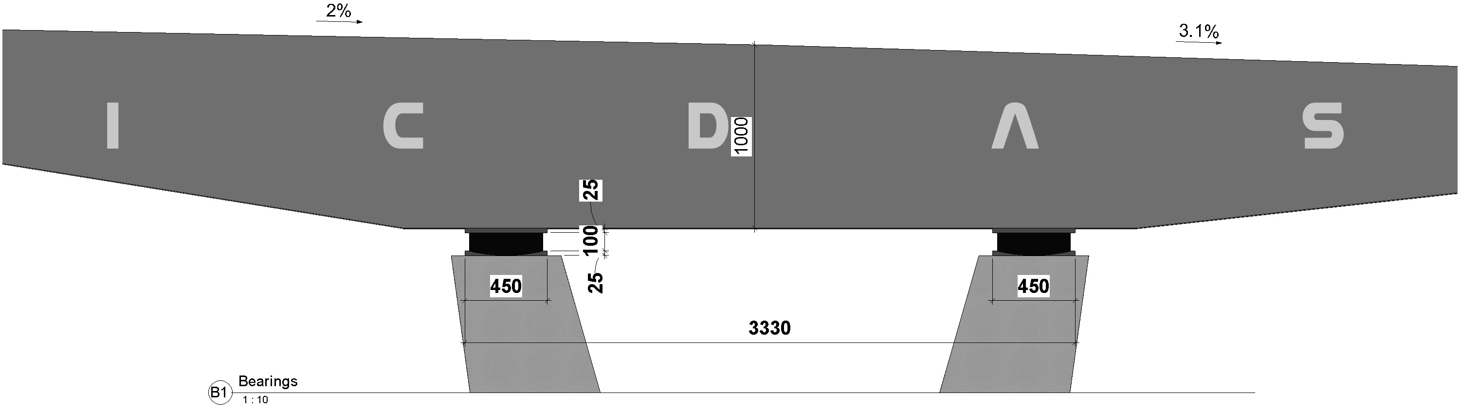
Input: The black values are input for the deck profile cross section.
Inputs of the deck cross section are show with the black values above, whereas program calculate the blue values. The cross section has two lanes of 2x3500mm on the left and the right side of the bridge center alignment. The slopes on the left and the right lane are both 2%.
Because of the double curves, this manual input needed to be adapted after the desired results. Input for the right lane width has been set to 7134 in Excel to obtain 7000mm in Revit. It is due to the longitudinal slopes 100mm down for each step point of 2000mm (5%), have been given manually. Also, the input for the right lane slopes has been subtracted 105mm in the Excel Corridor file. The final corrected Z-data in Excel columns should be directly obtained from Civil 3D in a project case.
Check of geometry for multi-slopes on top of deck profile are described below. The concrete deck locates 110mm below top of pavement. The one-sided slope on top of deck is 2% count from the edge beam inner points to the center STL, i.e. a vertical distance of 7000*2%=140mm.
On the left side, at the edge beam inner point: 30+110=140mm ü
On the right side, at the edge beam inner point: 250-110=140mm ü
Further, the input contra slope 11.1% on the right side gives 540*11.1%=60mm ü
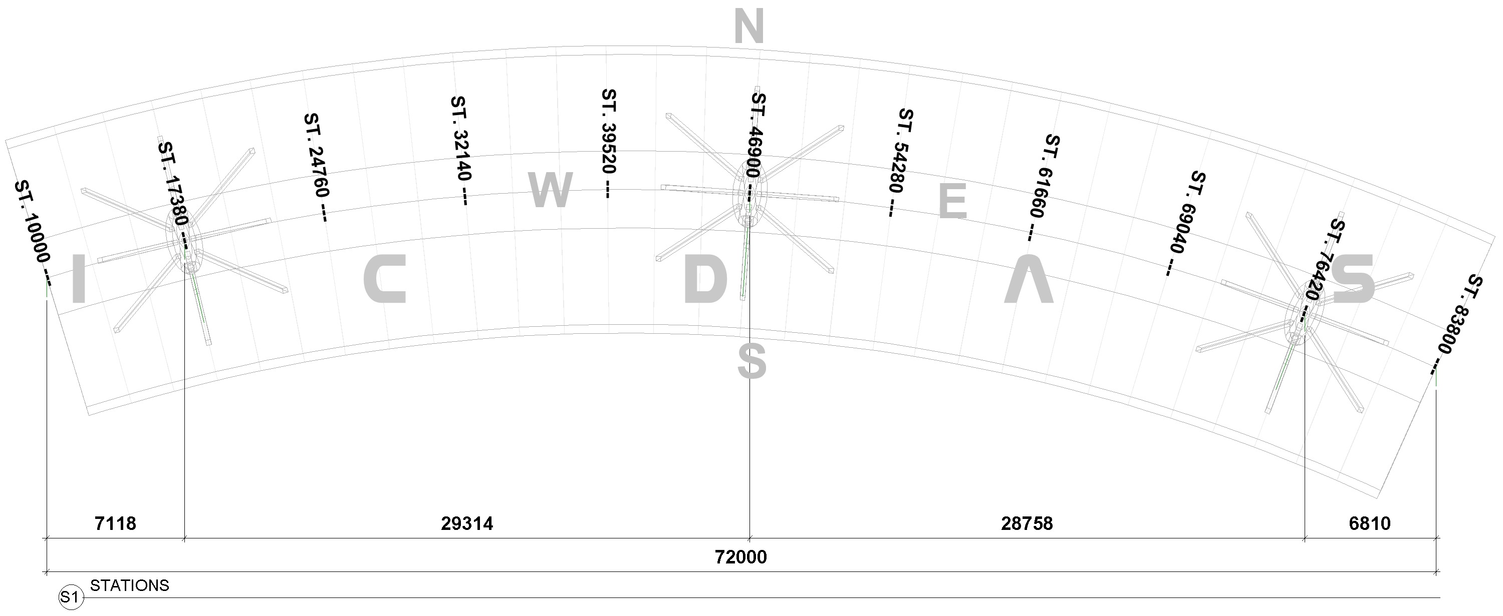
Below show 30 steps of 2460mm created by program the circle alignment in top view. 
Output: 31 profiles created the bridge corridor
In ICDAS input, 31 profiles have been given (red). As many profiles, as good for the program to fit the designed bridge to the road alignment. However, Dynamo Revit does not crash even for input of 3 profiles only (2 segments of deck). Also in ICDAS input, the total horizontal length of the circle is 72mm, which is input in 2m point step. It gives a segment length of 72000/(31-1)=2400mm. The above figure shows 2460mm calculated by the program as the curved length at the centre of the bridge.

Output: Stations along alignment.
From the above created segments length, ICDAS creates the stations at every three segments along the alignment. The station assumes to start at the start of the deck, called ST. 10000mm. Note that the station values normally are given in Meters, and big values. Here to keep the values simple to read, the start station is set to be 10m. Note further that the current Dynamo Revit code does not considered the station values, but work only on (X, Y, Z).

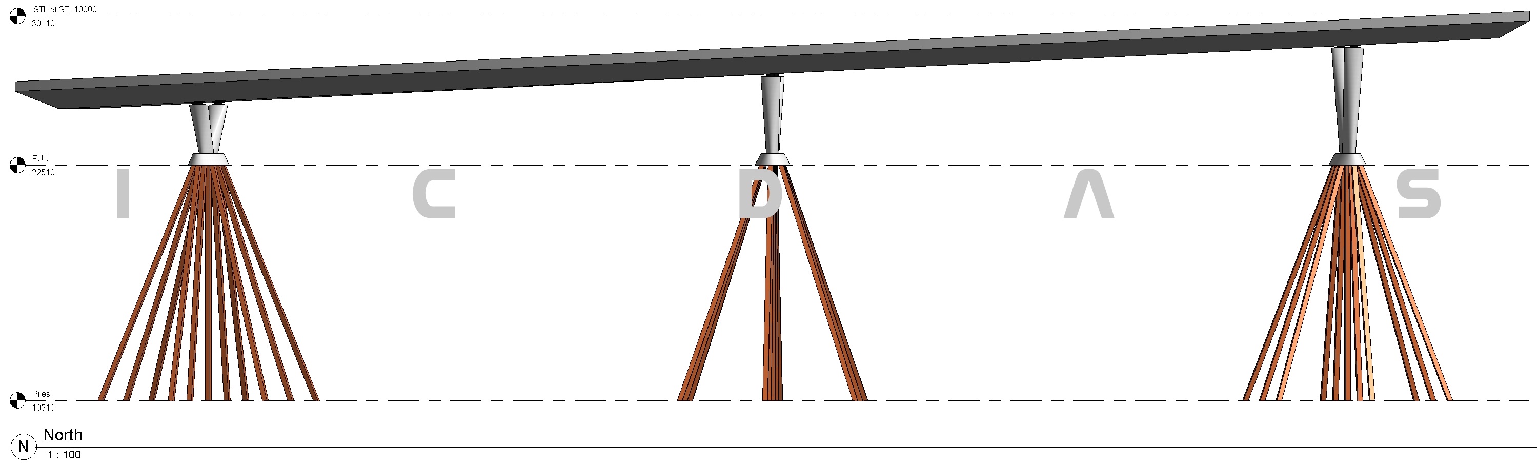
View S: South view elevation. 
View N: North view elevation.
Once the double curved deck created, ICDAS load the piles, piers, and bearings into the project file where the curved deck family has also been loaded. ICDAS Bridge Library provide a large option of piles, piers, and bearings which are predesigned ready to load into any project file. ICDAS Bridges has no limited number of spans. This example illustrates the two curved spans (and the cantilevers) but it is as easy to load the other spans on the bridge. Dynamo Revit has successfully created the curved deck slopping down 5% in South View elevation.
To check the vertical elevation 30000mm at alignment highest point, and 26400 lowest point on bridge deck: 30000 - 72000*5/100 = 26400mm ü where 72000mm is the input horizontal length of the bridge deck.

View WE: West & East view elevation.
3D Bridge using ICDAS Revit ensure the users correctness of the geometry. Elevation East and Vest are automatically created as two of many associated views from the 3D model. Levels on top of deck are precise the same values in the Excel Corridor input. 
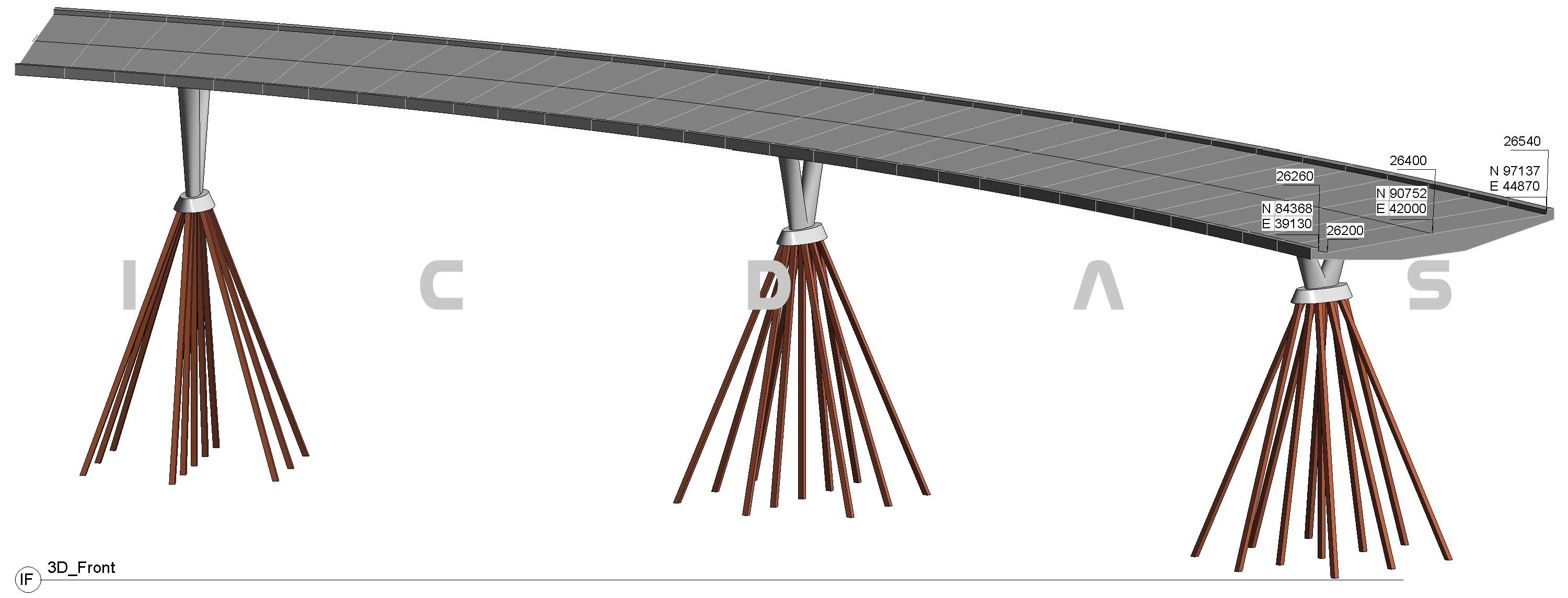
View IF: Isometry Front 3D view.

View IL: Isometry Left 3D view.
In Revit default 3D view, the users can free orbit the model to control connections of all bridge elements from which all 2D sectional drawings are layout. In point of design view in ICDAS Bridges, or any ICDAS model, the 2D sectional drawings are not of interest, since they are created from the 3D model. One can easy create whatever section in Revit and take whatever dimension he/she needs to know. Most interesting in ICDAS Bridges using Dynamo Revit technology is that, you can store as many corridors in Excel input as you wish. It is useful when engineers do often many works when the alignment of the bridge deck is changed, and to compare the changes. ICDAS Dynamo will create the double curved deck immediately, for any selected corridor sheet in Excel input. |