|
S o f t w a r e f o r a u t o m a t i c c r e a t i o n o f m o d e l s u s i n g p a r a m e t r i c d a t a
| 123456789_123456789_1 | 123456789 | Concrete Bridge Software
BIM Model (Geometry) |  ICDAS COB 2024.00R ICDAS COB 2024.00R
Road Bridge Model Examples | | | | 123456789_123456789_123456789_123456789_123456789_123 | 123456789_123456789_123456789_123456789_123456789_123456789_12345
|
123456789_123456789_1 | 123456789 | | Concrete Bridge Model Examples
Model description
Input
BIM model
Analysis model
Landscape model
ICDAS Basis of Design
Workflow of Software
Additional features
Rendering, Animation &
Vitural Reality
Case study
Trial Version
Subscription
| |
3D Reinforcement
This section presents 3D reinforcement in ICDAS Concrete Bridge (COB). To study step-by-step how to create all of the 3D reinforcement in a concrete deck please refer to the ICDAS COB manual including in your subscription.
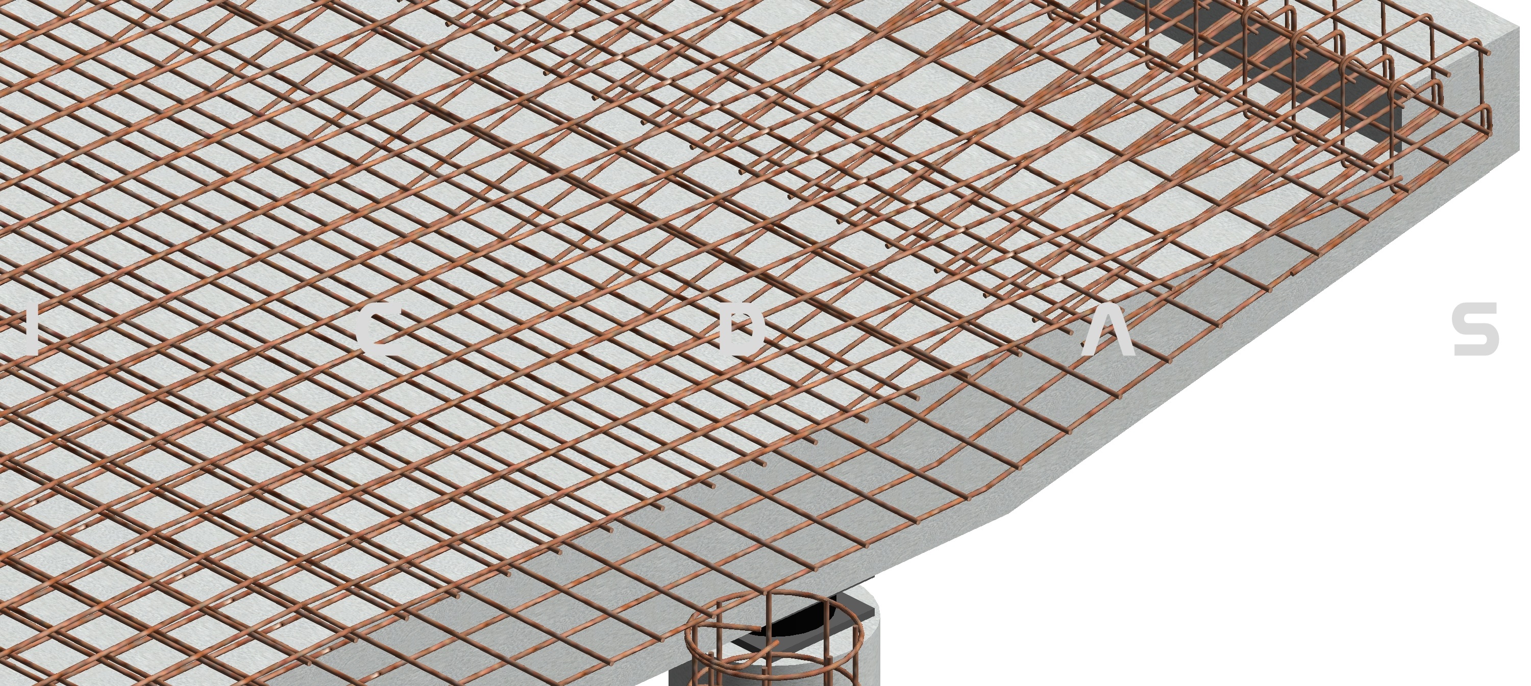
Before reading about 3D reinforcement in Revit, let us first resume how to determine the required reinforcement in a concrete bridge. In concrete bridges analyses, all computations will end to design the required reinforcement. Determination of the reinforcement required a FEM model of the bridge including loads on bridge described in the previous sections. This model is automatically created by ICDAS on LUSAS software. The quantities of reinforcement are then depended on behaviors of the bridge in SLS, ULS, ALS and FLS combinations of loads. Further, theory of elasticity and plasticity are both employed for verifications of concrete and reinforcement in SLS and ULS loads combinations for a given code (e.g. Eurocodes). For this purpose, a clear 3D reinforcement drawing needed to be prepared for LUSAS post processing. Once the optimal reinforcement have been verified, the users can easily modified the 3D rebar model which is concurrently created and modified in Revit. Below is an example of creation of rebar in Revit as the only focus. 
A section of concrete bridge of 10.069 m length and 9m width modeled as an example, see figure below (enlarge). |

Rebar and Concrete Dimensions 8000 pixels 

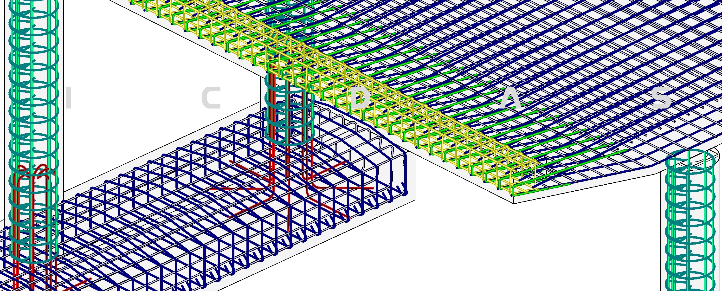
Figure: Auto detect rebar data in 2D section drawing from the designed 3D model. | | | | | 123456789_123456789_1 | 123456789 | Having dimensions of concrete one can calculate the quantity of rebar, e.g. (18-1)*200=3400 shown on the cross section above, top of deck, right side. 18 and 200 is the number and spacing of the longitudinal rebar, which are input in Revit. Further, the type 16 500S is also chosen, where 16mm is the diameter and 500 is the yield stress 500MPa of the mild steel, among a long list of options and modifications. Thus, using Revit 3D reinforcement, we create quantity - type - spacing - rebar number below a surface of concrete element. As the result, Revit automatically annotate 18 - 16 500S @200mm - 01 when we mouse on the rebar for the annotation. The rebar number 01 is automatically count by Revit based on "Partition" defined by the users. It is a free text e.g. DSTop, DSBot, DYTop, DYBot, Column Verical, Column Stirrup and so on, where "D" stands for deck, S for longitudinal and Y for transversal direction of the concrete element. Once a partition of rebar is created, the users can further assign an override color to separate it form the other partitions. Also the partitions the users will apply to create schedule for the rebar (quantity in m3). In alt, Revit 3D reinforcement provide all information and drawings the users wish for documentation of the reinforcement.
View styles
Further, Revit allows different view styles for 2D section drawings from the 3D model. It helps us to keep in mind place for the concrete, which is easy to overlook with 2D wire frame view style. |
| | | Schedule of reinforcement quantity Once a partition of rebar created, you can add it to schedule for reinforcement of the bridge. Example below show partition "Foundation Top" below the West pier. There are 4 rebar created in the center, 3 on each inclining side, which are reported in the Quantity column. Further, Type, Spacing, Rebar Number, Volume and Total Bar Length are also reported in the schedule. Once these rebar are updated, the schedule will also be automatically updated.
Refer to ICDAS COB subscription for step-by-step manual of creation of 3D reinforcement in concrete bridges.
| 
Figure: Automatic creation of schedule of reinforcement quantity, spacing, volume, total length and so on. | | 123456789_123456789_1 | 1234567 | 123456789_123456789_123456789_123456789_123456789_123456789_1 | |
| | | Static Documentation
Analysis model is fundamental for a static documentation. Automatic model creation ensure global dimensions of the bridge and local thicknesses of the elements are the same in Revit and in LUSAS for the first analysis. Working with static documentation can lead to changes in dimensions and thicknesses. These changes are detected by LUSAS, and need to be modify in Revit accordingly, and manually, for the ongoing analysis. |
However, the case the change is a new updating alignments which are quite different from the beginning, it is the best that the users update ICDAS input and create the two new models again. List of verifications for concrete and reinforcement are outlined in ICDAS Basis of Design for pedestrian bridges, road way bridges and railway bridges as well.
See also Analysis model for Arch Bridges. | | 123456789_123456789_1 | 1234567 | 123456789_123456789_123456789_123456789_123456789_123456789_1234 | Updated 20-06-2018 |
| 123456789_123456789_1 | 1234567 |
ICDAS Hans Erik Nielsens Vej 3 DK-3650 Ølstykke E-mail: th@icdas.dk Tel.: +45 60 53 83 79 CVR no.: 34436169 | | | | 123456789_123456789_123456789_123456789_123456789_123456789_123456789_123456789_123456789_123456789_123456789_123456789_123456789_123456789_
|
|