S o f t w a r e     f o r     a u t o m a t i c     c r e a t i o n     o f     m o d e l s     u s i n g     p a r a m e t r i c     d a t a

123456789_123456789_1123456789Wind Turbine Foundation Software

Analysis model
ICDAS WTF 2017.00R

Page   1    2    3    4    5
  123456789_123456789_123456789_123456789_123456789_123456789_123456789
123456789_123456789_123456789_123456789_123456789

123456789_123456789_1123456789 

WTF Model Examples


Model description


Input


Geometry model


Analysis model


Landscape model


ICDAS Basis of Design


Workflow of Software


Additional features


Rendering & Animation 


Trial Version
 

Case Study 


Subscription


Automatic Support Creation


Once the FEM mesh, thickness and material have been automatically created in Lusas, support conditions

are the next attributes to be on focus.


Soil as volume elements


The soil that supports a foundation structure usually has finite stiffness, which also can be varying in depth.

WTF create boundary conditions as soil in volume elements automatically. Shows below are two examples

of soil shapes outlined just for demonstration of automatic model creation (brown). The conical shape has

input Offset given along the vertical layers, whereas the cylindrical shape has Offset=10m at layer 0 only,

see input figures below.


Conical soil below the base slab (special seabed condition or by arrangement)


Cylindrical cut of soil surrounding and below the base slab (10m)

FigureAutomatic volume elements creation for soil in Lusas.

123456789_123456789_1123456789123456789_123456789_123456789_123456789_123456789_123456789_12345123456789_123456789_123456789_123456789_123456789_1234


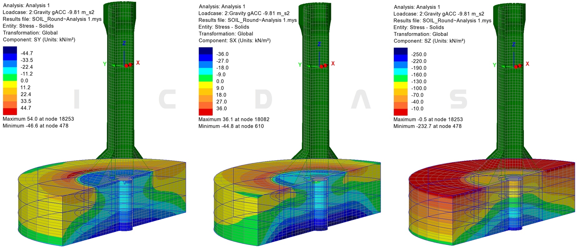
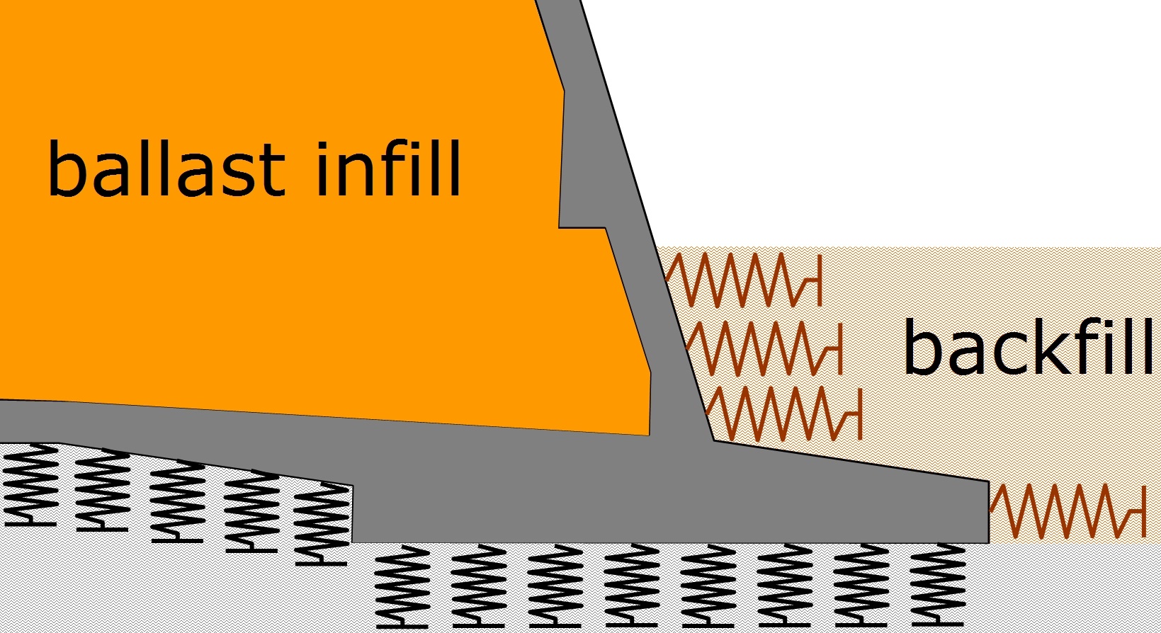
The soil elements are created below the base slab when

parameter Soil=1 is set in input. Otherwise the spring the

stiffness supported are employed if set Soil=0.


Depth (mm), E-modulus (kPa), density (kg/m3) and Offset

(mm) of a soil layer inputted in region "Soil layers and

properties" as shown to the right. There is unlimited number

of layers which can be entered in input. Examples here shows

3 layers a 3000mm where layer having a depth 350mm

below the base slab for master/slave coupling between the

soil and the slab elements.


Friction coefficients between the base slab and the soil

can be  obtained from geotechnical report of individual

project site. Also the support coefficients assuming below

the lowest layer of the soil. They are both entered in

input.


Soil behaves in nonlinear manner. It is common to deal

with the shear modulus of the soil, G, described in [1].

Reference is made to the Young's modulus of the soil E,

which relates to the shear modulus G through

E = 2G(1+ n). 


Figure: Input of conical soil model


Figure: Input of cylindrical soil model


123456789_123456789_1123456789

The stress solids in soil in the two examples below are from the gravity on the concrete foundation and the

considered soil volume density. Starting with simple load case will confirm the correctness of the model just

before analysis for soil-structure interaction.


As a rule of thumb, the natural frequency of the tower will be reduced by 0% to 5%, when the assumption
of a rigid foundation (fixed-ended tower) is replaced by a realistic finite soil elements. Under special conditions
this error may however be up to 20% cf. [1].


Figure: Stress solids in soil with conical model, SX, SY and SZ (kN/m2)


Figure: Stress solids in soil with cylindrical model, SX, SY and SZ (kN/m2)


123456789

Soil as spring stiffness


Foundation springs are nonlinear because properties of the

soil. It is common to apply linear spring stiffnesses, in which

case the stiffness values are chosen dependent on the strain

level that the soil will experience for the load case under

consideration, cf. [1].


The soil stiffness of the seabed is load dependent in a

nonlinear manner. Further, the loads assumed to be carry

by the foundation and transfer to the seabed - are again

depended on the soil stiffness.


Thus, some rerunning of the model are needed to assess

the results against different assumptions of the soil spring

stiffness. This issue is outlined in more detailed in

registered version where equations for the spring stiffness

are employed using additional data input for soil, cf. [1].


On the other hand, other predictions of spring stiffness can

also directly entered in Input which also easily can modified

in Lusas. Note that only the values in input file will be

documented in Revit sheets.


Determination of 6DOF spring stiffness is illustrated as

example for case of Thomton Bank Gravity Base Foundation:


- For vertical translation the interaction between the bottom

of the base slab and the created foundation layer in contact

with the soil of the seabed.


- For horizontal translation the friction between the base

slab and the foundation top layer. Also the interaction

between the conical slab at the bottom, its components

and the backfill, and also for the rotational stiffness.


FigureConical slab and base slab surrounding by backfill,
Thomton Bank Gravity Base Foundation.


Figure: Vertical and horizontal translation stiffness
(rotational stiffness not shown)

123456789_123456789_1


 123456789_123456789_123456789_123456789_123456789_123456789_12

 123456789_123456789_123456789_123456789_123456789_1234

123456789_123456789_1123456789

References

[1] Guidelines for Design of Wind Turbines, 2nd Edition, Foundation Stiffness p. 201-205 

[2] Lusas soil-structure interaction analysisGeotechnical / Soil-structure interaction modelling

[3] Lusas Söderström Tunnel Connector


Page   1    2    3    4    5

Updated 04-10-2016
  

123456789_123456789_123456789_123456789_123456789_123456789_123456789_123456789_123456789_123456789_123456789_1234


123456789_123456789_1123456789123456789_123456789_123456789_123456789_123456789_123456789_12123456789_123456789_123456789_123456789_123456789_1234


123456789_123456789_1123456789ICDAS  •  Hans Erik Nielsens Vej 3  •  DK-3650 Ølstykke  •   E-mail: th@icdas.dk   •  Tel.: +45 29 90 92 96  •  CVR no.: 34436169