As increasing demands on Revit BIM model for bridges, ICDAS has improved new methods for creation of bridges in Revit. Also to answer the question about how complicated an ICDAS Revit bridge can be created, the Storstrom cable-stayed bridge has been chosen as an example. The following challenges are faced:
Double curved alignment horizontal radius 6197.75m and vertical radius 75200m. Two alignments for the railway and roadway are not parallel. The cable plane is not vertical due to the curved deck. Thickness of concrete deck box increased towards the pylon in curved alignment. Top of deck significantly changes level with the road side higher than the rail side. Cable posttensioning across the deck of over 26m at its maximum width. 3D Pier shape with top segment inclined in the same slope as the deck box two sides. Asymmetric thickness pylon fixed to the deck above the pier. Analysis model will smart combine Load model 71 for the railway, 1 and 3 for the roadway, to search the worst combination of all possible combinations.
The cable-stayed bridge has a single pylon carrying two concrete spans of 160m. The bridge deck girder is in concrete box deck. The bridge is a part of 3.84km link between two coasts of Masnedø and Falster in Zealand Denmark, where the two approach bridges have a standard span of 80m, also in concrete box deck. The project costs 4.2 mia. DKK with EU support 112 mio. DKK. DISSING+WEITLING has won the suggested solution in 2012 and COWI implement the Tender Design for The Danish Road Directorate (DRD) as the client. The link is planned to construct in period 2017-2024. This example is focused only on the cable-stayed bridge of the link, where the supplied materials 2D PDF drawings from DRD are employed for the 3D model.
Geometry model of the Storstrom cable-stayed bridge

Figure: New alignment for the Storstrom link in Zealand Denmark 2017-2024 (left), cf. The Danish Road Directorate.

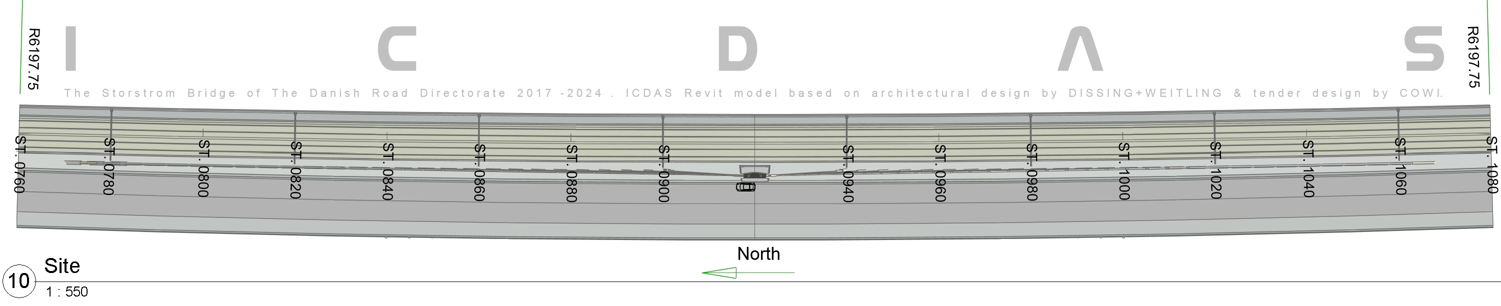
Figure 10: Floor Plane Site View of the cable-stayed bridge from ST. 760 to 920 (+299000).
The cable-stayed bridge of the Storstrom link has a curved alignment of horizontal radius 6197.75m. The alignment is created in Floor Plane Site View (Z=0) and be the main input for ICDAS Revit bridge. The stations are increased towards South starting at ST. 760 from the North, ending at ST. 1080 at the South (+299000m). The pylon is located in the center at ST. 920. The girder has a curved length of 320m measured on the alignment located at center of railway.

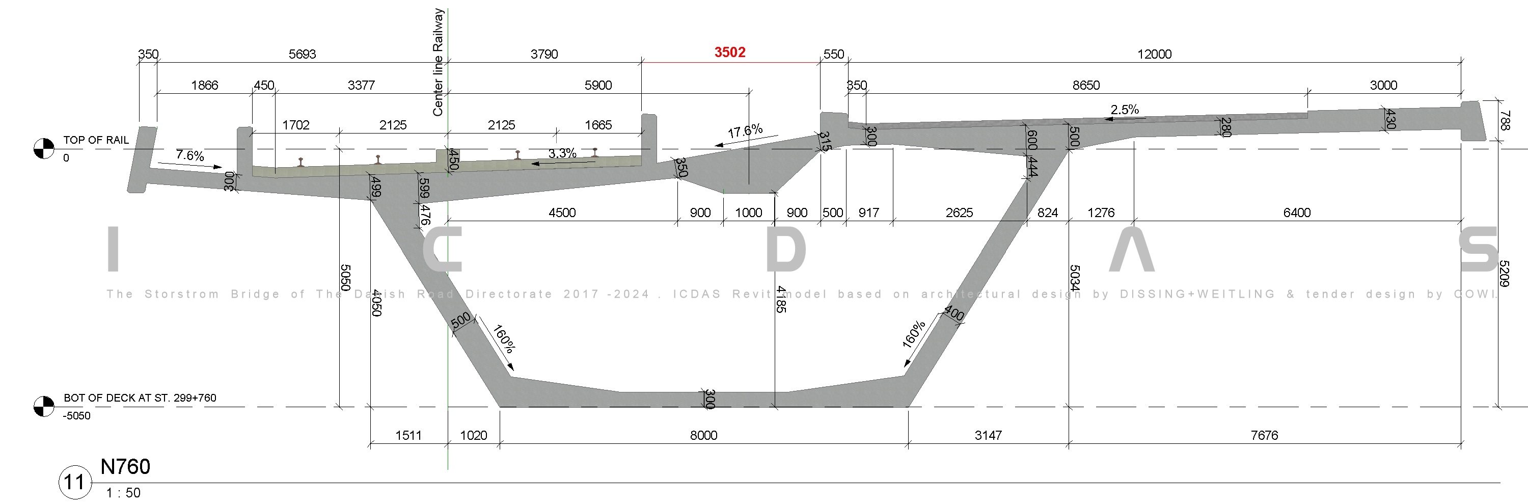
Figure 11: Cross section at Pylon station 760 (+299000)

Figure 12: Cross section at Pylon station 920 (+299000)
The above two figures are input for the bridge deck girder. Elevations are given in relative coordinate which can be updated to global coordinate at any time at Revit Project Base Point. The following dimensions are the key geometry of the bridge.
The deck girder has varying width from 3502 to 4167mm at station 760 and 920m, respectively. These values are highlighted in red in the above two figures.
All slopes on top of deck are kept unchanged between these two stations.
The railway side (5693+3790) and the roadway side 12000mm keep the width unchanged.
The internal depth of box 4185mm keep unchanged between the two stations, also the height (788+5209)mm at the end on the roadway side.
The thicknesses of concrete box increase from ST. 760 to ST. 920
Relative elevation 0 assumed to be 450mm above top of concrete at Center line Rail at ST. 760.
The cross section raise 170mm at ST. 920 (center of alignment of the cable-stayed bridge) due to the vertical radius 75200m. As a result, the distance 1020 at ST. 760 reduced to 1000mm at ST. 920 which are shown at the lower left corner in the above two Figures.
The cross section N760 is reused at ST. S1080 at the South end due to symmetry.
With input as the curved alignment, the cross sections and ST. 760, 920 and 1080, ICDAS Revit create a curved 3D bridge deck of 320m from which any cross section can be generated for the dimensions.

Figure 13: The Storstrom cable-stayed bridge
Still in project file, the cables, the pylon, the pier and the masts are loaded into the Storstrom cable-stayed bridge as shown above. For further details refer to ICDAS CSB subscription for the manual and ICDAS library of bridge components. The 27 cable-stayed are attached in 5m distances on the girder and 1.5m at the pylon.

Figure 14: Section Box at pylon
For each component loading in the bridge, the users can use Revit Section Box to control the geometry with 3D cut as shown above. Revit Section Box allow the users to zoom to any small box on the model. It helps the users to orbit the model limited by the section box much faster than the entire model. Shown above the section at the cut overrides with solid blue, and where the section box in this face (of 6 faces) is dragged closed to the cable North 1 to focus on the anchorage inside the box girder. 3D illustration shows the cable end attached to the girder not be in vertical plane but inclining towards the pylon. For the longest cable the working point of on the deck girder move 2957mm to the railway side compared to the point on the pylon. The above view also shows the pier top segment has the edge in the slope of the deck box side. The masts on the
railway are modelled in 40m distances.

Figure 15: Cable N1 Anchorage Components at Girder Section box above highlights the components at the anchorage where the concrete deck is hidden. The cable attaches to the deck by a top gusset, two RHS 300x300x12.5 and two bottom connections. A bottom connection has 2 plates attached to the RHS tube. These plates are further attached to 2x11K25 rebar which are run out from the concrete deck. These rebar are casted in the concrete deck in U-shape which are not shown. The top gusset is located exactly on a side of the cross beam. Note that the cross beam on the roadside has varying length due to the varying width of the deck. The varying length is located at the end of the cross beam on the roadway side. The above figure shows only the surfacing pavement on the roadway side.
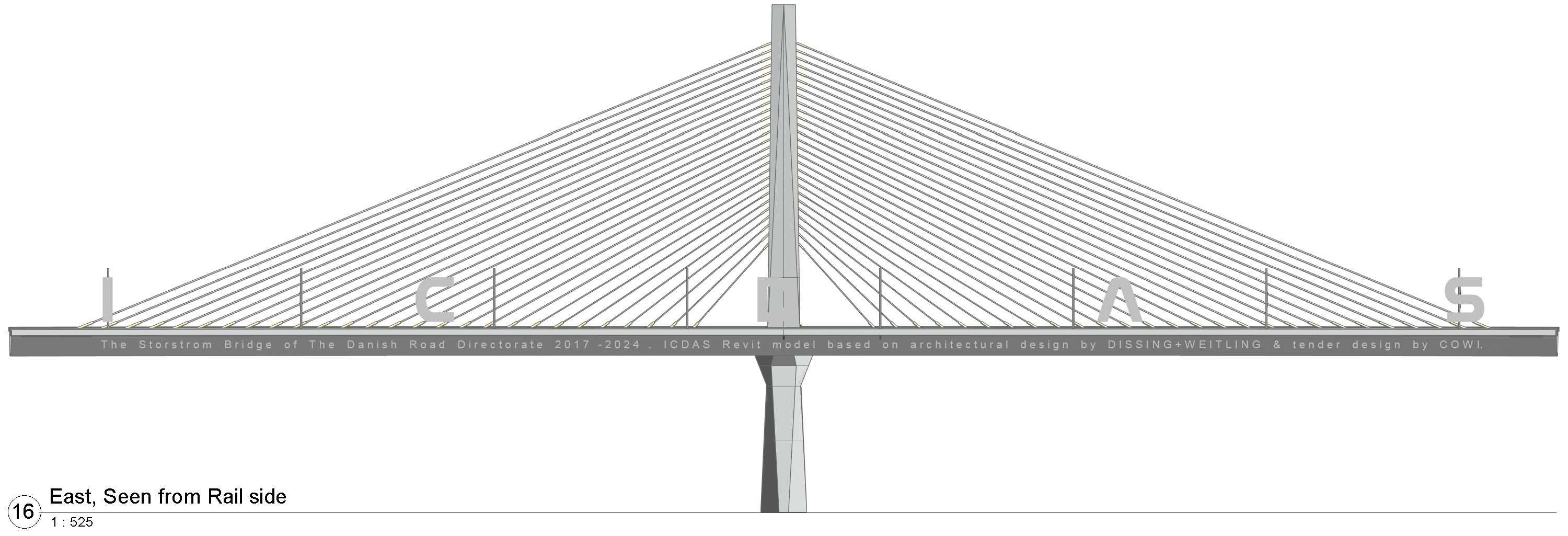
Figure 16: Elevation East, as seen from the railway side.

Figure 17: Elevation West, as seen from the roadway side.
As control on the vertical curve of the girder, the West figure shows vertical distances Z from horizontal to bottom of deck.
Z=0 assumed at start of deck ST. 760, and the measures are taken at 20m distance towards the pylon at ST. 920, which
has Z=170mm. Knowing (radius, chord length) = (75200, 320)m, the circular equation gives exactly the above distances.
As seen from the railway and the roadway side, the pier has different shape.

Figure 18: Elevation North & South As seen from the North and the South, the pier has mirror edge lines. The 3D pier has been modelled with 2D dimensions given by The Danish Road Directorate PDF materials. The RHS tubes attach the cable to concrete deck has been modelled for the cable North 1 only.

Figure: The new Storstrom Bridge, ICDAS Revit LIVE model.
Updated 19-06-2018 |